BlogArticles
A practical introduction to BIM for architects and industry professionals
14 Feb 2026 (updated 7 Nov 2026) · Maks, architect and BIM manager. 10+ years working with Revit and BIM on architectural projects.
A simplified overview of Building Information Modelling: what it is, what it is not, and how to keep the process useful on live projects.
BIM (Building Information Modelling) is a process for creating and managing information on a construction project throughout its whole life cycle.
I have spent more than 10 years as an architect working with Revit and covering BIM management. This article is for architects and industry professionals who need a simplified overview of BIM, and for anyone less familiar who needs an initial introduction. This is my attempt to bring clarity in a simple manner.
What is BIM?
BIM = Building Information Modelling.
The model is a coordinated digital description of the building, made of 3D models and structured data. The process around it covers how that information is created, shared and handed over.
References: What is Building Information Modelling (BIM)?, NBS and ISO 19650-1:2018, information management using BIM. For UK guidance, see the UK BIM Framework.
Here are the core principles:
- Building = the project or design.
- Information = 3D components hosting data, or dynamic data such as dimensions.
- Modelling = the actual 3D elements that form the object.
The image below shows it as a triangle. A model element sits at one corner and hosts the data. The geometry is shown on the plan, and the same data fills the schedule. All three are connected in one data model, so change the element and the plan and the schedule follow. This is the essence of BIM.
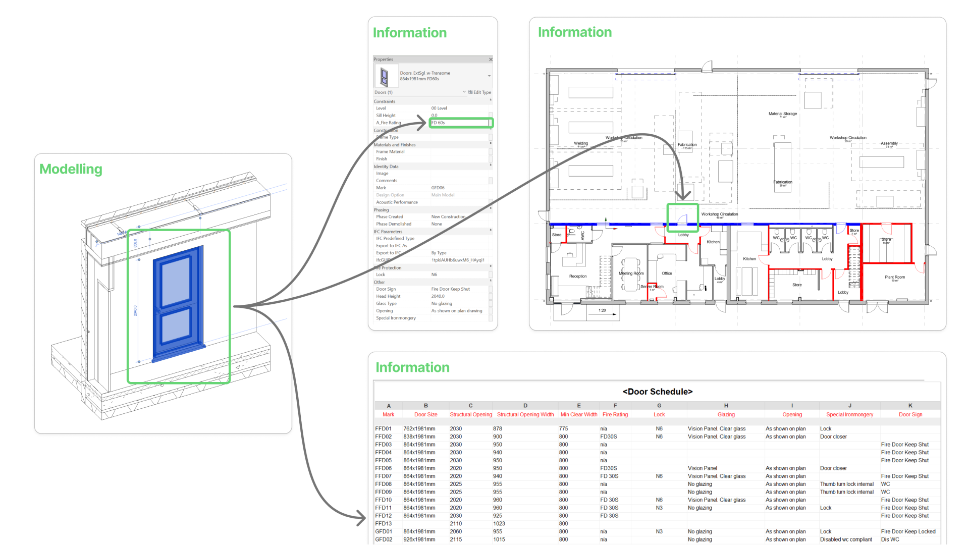
Image: Systemais Team
Is my team BIM capable?
Yes, if your BIM software (or your consultant's) lets objects be modelled in 3D and carry data. Then you are BIM-capable and working in BIM. The last piece is that you can export the model as IFC, a universal file format, which is typically used for model federation. We will discuss the federated model later in the article.
Who are the key BIM stakeholders?
Key BIM stakeholders can be defined in the following groups:
- Client BIM team. Typically connected directly to the facility management team. More and more facility managers are using BIM models and the data in them to run the building. On government-procured projects this is often compulsory.
- Model authors. The people who actually 3D model the elements. Typically design team consultants, also often referred to as the "task team".
- BIM managers. The people overseeing the process.
- Contractors BIM team. During the construction stage, BIM workflows can become a lot more advanced and serve many purposes.
- Sub-contractors.
How is design information produced in BIM?
This is where theory and practice start to split. The best practice version looks like this:
- Drawings in BIM are viewports into the state of the model. Annotations (also known as "tags" on the drawing if referring to Revit) are a direct, dynamic reflection of element data.
- Schedules are a direct, dynamic reflection of element data.
In practice, model data often gets overwritten manually. This happens because of software limitations, high complexity, and the pressure to deliver on short timescales. Drawings then become only a partial reflection of the model, and drift further from the single point of truth. We spend an exhausting amount of time policing this, and it often feels like a losing battle. I put much of that down to software limitations that make data integrity harder than it should be.
The construction industry is still very stone-age in some aspects. After developing a data-rich BIM model, we still flatten the information into PDFs as the primary design information packages. The craziest thing I have seen on site was a contractor's team using PDF plans to manually measure room areas. I am not sure of the exact context, but those take-offs are usually done in minutes inside the model. We are modelling Ferraris and using them like horse-drawn carriages, because of these legacy workflows.
Having said that, from experience of observing the industry, I understand why. A PDF is fixed, simple and printable. No fitter on site walks around with an iPad, an electric grinder in the other hand, navigating a model.
Nobody signs a contract based on a federated model either. Models are complex data sets with hundreds of thousands of objects and data cells, and we do not have an army of BIM modellers to manage that process. So the only reliable contractual way of sharing data is still the PDF.
BIM Execution Plans, LOD and COBie: the boring (but important) stuff
What is a BEP (BIM Execution Plan)?
The most boring document in the world. Almost no one reads it, and it is still important. It describes how BIM workflows will be implemented: which software, what 3D resolution, what data, and who is responsible. Keep these short, lean, and focused.
In practice there are usually two BEPs: a pre-contract BEP and a post-contract BEP. This is because you can typically expect two different parties to undertake the BIM manager role. They change at specific stages during the project:
- RIBA 2 to 4, pre-contract. The lead designer, typically, and this should be agreed in the appointment terms. Whoever writes the BEP is the BIM manager.
- RIBA 5 to 6, post-contract. After the contractor has been appointed. The main contractor is responsible for preparing the BEP and managing the process.
Pre-contract BEP. This typically spans RIBA stages 2 to 4. The BIM manager is the lead designer or a third party appointed by them, and the focus is design collaboration and design development. The procedures do not need to be complicated, they can be very simple. Most big practices already use BIM and have internal QA processes, so there is no need for a 70 page BEP stating the same thing.
No matter what you write in the BEP, and no matter what responsibility matrices you add, the consultant's original agreed scope is the main factor. The BEP will not override those contractual responsibilities. Full stop.
Post-contract BEP. This spans from RIBA stage 5 all the way to handover. Here the contractor, usually the managing contractor, should take responsibility for the BEP and the BIM manager role. Construction brings a lot of complex processes, and BIM workflows can be used for many of them. The focus also shifts to the employer's requirements for delivery.
What is LOD (level of detail)?
According to NBS, LOD is the level of detail, which covers the graphical side of the model. Its partner, LOI, is the level of information, which covers the non graphical data. The NBS BIM Toolkit gave these indicative bandings single digit numbers from 2 to 5, in line with the BIM Protocol and the PAS 1192 documents. NBS also says these terms are now superseded by ISO 19650, BS EN 17412-1 and the "Level of Information Need" approach, but they are still a useful shorthand. The idea behind all of it is to provide the right amount of detail at the right project stage. Too much geometric detail at the wrong stage wastes time, team effort and computing resources.
Reference: Level of detail (LOD) and digital plans of work, NBS
That is the official version. On live projects, people talk about it more simply. Level of Development (or Detail) describes how detailed a model is, both graphically and in data. It is often set as LOD 100, LOD 200, LOD 300, and so on. LOD 500 is referenced as fabrication-level resolution, and it is rarely practical or necessary. For most architectural work, around LOD 300 is more than enough.
The more detailed a model becomes, the more resource it takes to create, manage, and maintain. It takes more computing resources as well.
The more traditional way of referring to LOD is levels 100, 200, 300, 400 and 500. NBS now uses LOD levels 1, 2, 3, 4 and 5. It is basically exactly the same thing with two zeros removed. I am not sure why this happened in the first place.
I am also not sure why level 100 (or 1) exists. The model geometry is too crude and coarse to make any logical sense. It is probably only logical where you have to model a huge amount of geometry, like a large city, and anything beyond that resolution would be impractical. In the design of buildings, level 3 is the best logical midpoint.
Level 500 (or 5) is the fabrication level of detail. For example, a steel or staircase subcontractor will model every single nut, bolt and plate, because they actually need to manufacture it and quantify it for delivery.
So it does not really matter what LOD you state in the BEP. Every competent consultant will make that decision themselves in the first place. If something does not look right on your plans, you model it to a proper level of resolution anyway. This should be left to the consultant team and the model holders to decide.
The key mistakes with level of detail are undermodelling and overmodelling. A good example of overmodelling is a furniture supplier offering a downloadable Revit family. Each chair is built as an almost perfect LOD 500 model. Download one, load it into your project, and suddenly you need to multiply it 500 times. This makes architects' models very heavy and slow.
What is model classification (and COBie)?
Model classification sounds complicated, but in principle it is relatively simple. To classify a model, designers only need to assign specific data to the model elements. It can be text, a number, a reference number or a description. It follows a set of rules that says which data goes against which element on which project.
Typical classification examples: classification codes, installation date, warranty length, and similar fields. If model authors already follow BIM best practice, much of that information is already in the model. It only needs copying into the standard COBie fields, rather than becoming a separate piece of work.
COBie is one of the best known industry examples. It has its own set of fields that you add to your model, and you fill them with the relevant information on the model elements. That information is then typically used for facility management, where the FM team will be using BIM for exactly this purpose. COBie is compulsory on some government procured projects in the UK, such as schools.
Read more about COBie: What is COBie?, NBS
What is a BIM survey?
These need to be considered carefully. A BIM survey means the survey information is delivered as natively modelled 3D geometry. It could be site topography, below ground services or the existing building fabric.
Typically surveyors first do a traditional survey and then convert it into a three dimensional BIM model. Both remain as relevant survey information, side by side. A technique you will often hear about is scan to BIM. The surveyors scan the building and produce a point cloud, load the scans into the modelling software, and create native geometry from them, native to the selected BIM modelling software.
Typically you want to commission the traditional CAD survey as your baseline. Then ask yourself: do you actually need a BIM survey?
Things to consider:
- Survey specification. The useful output is typically a native survey model of the existing building fabric, so architects and the other design team members do not need to model the existing geometry from scratch. The specifics of the output are where the complexity is. Consider carefully which outputs are required, and in what format. Write a detailed specification so the surveyor knows what to deliver. It is quite tricky to get right and there are a lot of lessons learned, so we will cover this topic in a separate article.
- Timing. The key problem is timely procurement and delivery of the native BIM survey model. Surveys are often commissioned too late, after the design model has already been built from imprecise 2D CAD. The model authors have progressed with their own models in parallel and now need to inherit the survey model. Good luck reconciling those. It is a very complex and big problem.
- Cost. A BIM survey adds cost on top of the traditional survey.
Common BIM misconceptions
What is a federated model?
Different stakeholders may use different authoring software. A federated model combines their outputs in a viewer. You cannot edit it. You can only review it.
This is where the IFC export format is typically considered the unified standard. Consultants export their models from their native authoring software as IFC files, and these can be federated into one combined model for review and coordination.
In practice everything is a lot more complicated: different formats, different coordinate systems, and the list goes on. Let's not go down that rabbit hole.
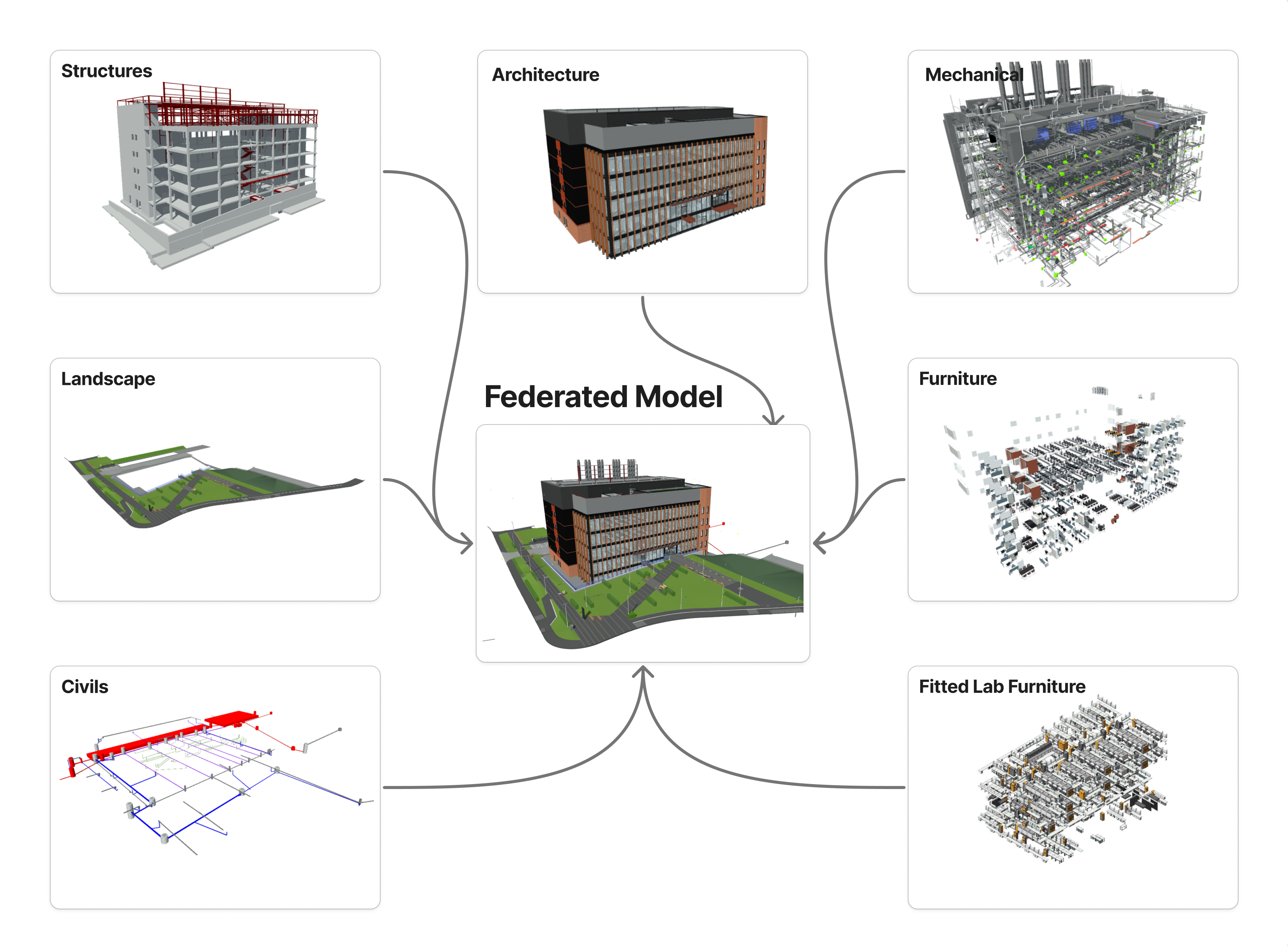
The image below shows the idea. Seven separate models (structures, architecture, mechanical, landscape, civils, furniture and fitted lab furniture) feed into one federated model in the centre.
Federated model diagram. Image credit: Associated Architects.
Is clash detection the point of BIM?
There is still an obsession with clash detection: who is going to undertake it, and who is responsible for managing the process. What we need to understand is that you are taking hard geometry and detecting where it intersects with other geometry. Those intersections are what get called clashes.
The problem is that the software is not intelligent enough to tell the difference between a true design coordination issue and a simple geometry versus geometry intersection. You can end up with 1,000 hard clashes, and about 5 of them are real issues. The rest are not worth reviewing, because they will never reach site and will never be a problem.
The real problem is something else. A late design change that sends additional services through shear walls is a good example. The openings (builders' work openings) need careful consideration by structural engineers, and they cannot simply be introduced on site.
From experience, clash detection is not what we should be focusing on. The focus should be a careful selection of different techniques for reviewing models and coordinating the designs.
Revit is not BIM
Revit is modelling software that can comply with BIM principles. The majority of companies in the UK use it. An NBS survey of 225 NBS National BIM Library users, undertaken between October and November 2013, found that 69% used Autodesk Revit as their primary 3D geometric modelling platform. The survey is from 2013 and the NBS page has since been archived.
Reference: NBS survey sheds light on BIM platform usage, NBS
Revit native elements are modelled in Revit, not imported through a shortcut. Sometimes native modelling is impractical, and that is fine. If a subcontractor does not use Revit, they are still doing BIM when their model is 3D, carries data, and can be exchanged as IFC.
What are BIM Levels 1, 2 and 3?
Levels were the industry's attempt to bring order to a fairly complex topic and describe the maturity of BIM. First came the term BIM itself, Building Information Modelling. Then came BIM Levels 1 to 3, an attempt to grade how advanced a team's BIM is. Level 1 is 2D CAD, which does not meet the definition of BIM above. Level 2 is the one you hear most often. Level 3 was meant to be a level of shared modelling and data that current tools do not really support. The levels have since been scrapped, because there is no real logic to them and it is close to impossible to define them in the first place.
Stop using levels. Avoid saying "Level 2" in particular. What is Level 2, or Level 1, in this context? Nobody can really answer that. Instead of describing the maturity of BIM with levels, focus on the BIM requirements for the specific project.
What is a CDE (common data environment)?
CDE (common data environment) procedures are essentially described under BIM, but this is not really BIM. It is project information management, including ISO 19650, and it typically refers to document and drawing management procedures rather than three dimensional geometry management.
In simple terms, a CDE is a digital platform where project stakeholders exchange and share project information, including drawings. Some would suggest that model viewers and software for federated models are also part of a CDE, but that is just confusion, so I suggest keeping it simple.
We discuss all of this in a lot more detail in a separate post: CDE explained simply.
Final thoughts
BIM solves problems, and it creates its own. Someone has to manage the process, it will not look after itself.
Hopefully this article lived up to your expectations. I tried to explain BIM procedures as simply as possible, while still covering all the major aspects. If you have any questions, please feel free to contact me.
Subscribe
Occasional notes on practice tools and systems. No spam.